
 Início
 》》》》》》》
1 Tutorials ZBrush Model, Sculpt and Texture a Demon-like Monster in 3ds Max and ZBrush – Day 1 Qui Jan 27, 2011 9:15 pm
Admin

Admin
Tutorial Details
Tweet
reddit this
Final Product What You'll Be Creating

//This is a multi-part tutorial on creating a Demon-like ‘Lok
Warrior’ with realistic muscle anatomy. In the first day of this
tutorial we will create a base mesh for our character using poly
modeling. In day two we will take this mesh into ZBrush and sculpt
intricate muscle anatomy. On day three we will texture the creature and
add the finishing touches to the artwork.
Let’s begin day 1 of this tutorial.
Step 1
I used two images from 3d.sk
to model the base mesh more accurately. I drew 2 planes, one from the
frontal view-point and one from the left view-point. With the exact
same length and width as the original photos, I applied the photos as
their textures, and then used the Move tool to view our image plane as
seen below.
Step 2
Start with a cylinder with 5 height segments.
Step 3
From the front viewport delete the half side of your model so that
you can add a symmetry modifier. Click on ‘Editable Poly Vertex Level’
and now we are ready to use some very handy tools: move-scale-rotate,
and make the shape of the cylinder fit the image body. Press Ctrl+E and
then you need to delete the four polygons. Your final result will be
similar to image below.
Step 4
Now select and extrude that front edge using Shift + Move; as you
can see on below image, in blue color, try to work in both the front
and left viewport. When you are near to back part edge, use ‘Bridge’ to
connect the edges when both are selected.
Step 5
Now for the leg. Extrude the selected edges by holding the Shift key
down on your keyboard and use the move tool as show in the image below.
To help them stand out, I colored them in blue. When you are done, try
to form the leg from front and left viewports using the vertex
sub-object level and like before, move-scale-rotate them.
Step 6
For the arms, use the same method as the leg in the above instruction.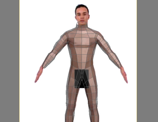
Step 7
For modeling the hand, I used a box with a poly count equal to the
arm border. In addition, I also changed the topology by cutting the
selected polygon below to have 3 quad Image in order to have all
fingers without having more segments from the box. Please note: If you
increase the box segment, you will have problems bridging that to the
arm because of the different polycount.
Step 8
Select and extrude/rotate each polygon to model the fingers.
Step 9
Attach the body to the hand. As you can see, the symmetry modifer
will mirror the hand for the other arm too. Using ‘Target weld’, weld
the hand vertexes to the arm vertexes. We don’t need the image planes
any more so you may delete them.
Step 10
Now it’s time to model the foot. For this we’ll use a cylinder.
Delete the top and bottom polygons and two more polygons, as shown
below.
Step 11
Now select those edges and with Cntl + the Move tool extrude them to look something like image below.
Step 12
Create new quad polygons using the cut tool on that polygon.
Step 13
Continue extruding edges and cutting just like before
Step 14
Now for the bottom part of the foot, extrude each side edge. Using ‘Target weld’ again use ‘cut’ for creating new polygons.
Step 15
Now cap the border and create 4 polygons by using ‘cut’.
Step 16
Bevel each polygon to create the toes.
Step 17
Attach and connect feet to body just the way we did before with the
hands. Tweak the vertexes using the move-scale-rotate tools and cut
ring edges using Ctrl+E. The result should be similar to image seen
below.
Step 18
Now it’s time to start the head. Because it is a low poly base mesh,
we won’t have many details on the face. Create a small plane and after
converting to an editable poly, start extruding edges and moving the
vertexes in both front and left view ports.
Step 19
Continue extruding edges and moving the vertexes.
Step 20
This is what we have so far:
Step 21
Continue with the head using the methods we previously used on the body.
Step 22
Select those polygons and extrude them. Create new polygons using ‘Cut’. After that, delete those polygons to start the horn.
google_protectAndRun("ads_core.google_render_ad", google_handleError, google_render_ad);
Step 23
Add a symmetry modifier to the head object and then select each
horn’s border. While holding the Shift key down, scale them in. Cap
them and ‘bevel’ them out three times each. Now is the time to make the
horn smaller; when you are done, you will need to tweak some vertexes
to create something like below.
Step 24
Add two spheres for the eyes and connect the head to the body just
as you did the hands and feet. Make sure to create new polygons so that
you will have enough vertexes to weld them.
Step 25
Now we have created the monster head with a human body. Delete one
finger and one toe, then cap and move polygons. For the foot
fingernails, simply bevel them twice.
Step 26
Now it is time to use ‘Unwrap UVW modifier’. Select the body and add
UVW modifier from modifier stack, but do not delete Symmetry. Go to the
materials panel, select a material and add ‘Checker’ to its diffuse
slot. Set the tile for both U and V to something like 20 or 30.
Step 27
Now we are ready to start UV mapping for our character. Turn off the
‘symmetry’ modifier then click on the ‘Face’ sub-level of ‘Unwrap UVW’
and select all the leg faces but leave one inner row and foot faces.
Step 28
Now, click on edit (you are in Edit UVWs window). Now, click ‘Quick
Planer map’ from Unwrap UVW modifier and use ‘Relax’ from the tools
menu of the Edit UVWs window several times. Use the rotate tool to
rotate the leg faces making sure that you selected all the faces first.
Step 29
Select the row of faces that you didn’t select earlier in Step 27
and click ‘Quick Planer map’. Relax, rotate and then move them.
Step 30
To have a better understanding about welding vertexes, click the
‘Display’ menu on the Edit UVWs window and check ‘Show Vertex
Connections’. Now if you select a vertex, you will see a number that
helps you to find the right vertex to weld.
Step 31
Right-click anywhere in the Edit UVWs window and select ‘Target
Weld’. Start welding vertexes of the leg and that row, check the
process in ‘Max, and move vertexes around if you see any stretching.
Step 32
Complete the same process for the foot. Select the top part faces of
foot and then click ‘Quick Planer map’ and then the bottom faces. Weld
their vertexes too and use scale to make them smaller. When you look at
the ‘Max viewport, the checkers should be almost the same size. You can
map the faces between the foot and fingers separately.
Step 33
Continue selecting faces and do mapping the same as before for upper body.
Step 34
Select the back body faces, then the arm and hand just the way we did before for leg and foot.
Step 35
Now move them very close to each other and start welding with ‘Show Vertex Connection’ on.
Step 36
Map the head with selecting faces and welding vertexes. In the image below you can see how this should look.
Step 37
Turn symmetry on – this will create a copy of what you did on
mapping. Check ‘Select element’ in the the ‘Edit UVWs’ window. Now
select each part and click on the ‘mirror horizontal’ tool. Weld the
body and head vertexes. Use the scale tool and then pack your UVs in
the work area.
Step 38
Click on the symmetry on top of our modifier stack and then
right-click and collapse all. Before exporting the model, make sure the
mesh has no holes by selecting/moving vertexes that were across the
mirror of symmetry before.
Step 39
Export the model as an OBJ file and import it into ZBrush 3.1. Use the OBJ Exporter settings below:
Day 2 Preview
In Day 2 of this multi-part tutorial we will bring the low-poly base
into ZBrush and begin sculpting powerful and realistic muscle anatomy
for the Lok Warrior.
]
- Program: 3ds Max, ZBrush
- Difficulty: Advanced
- Completion Time: 1-2 hours
Tweet
reddit this
Final Product What You'll Be Creating
//This is a multi-part tutorial on creating a Demon-like ‘Lok
Warrior’ with realistic muscle anatomy. In the first day of this
tutorial we will create a base mesh for our character using poly
modeling. In day two we will take this mesh into ZBrush and sculpt
intricate muscle anatomy. On day three we will texture the creature and
add the finishing touches to the artwork.
Let’s begin day 1 of this tutorial.
Step 1
I used two images from 3d.sk
to model the base mesh more accurately. I drew 2 planes, one from the
frontal view-point and one from the left view-point. With the exact
same length and width as the original photos, I applied the photos as
their textures, and then used the Move tool to view our image plane as
seen below.
Step 2
Start with a cylinder with 5 height segments.
Step 3
From the front viewport delete the half side of your model so that
you can add a symmetry modifier. Click on ‘Editable Poly Vertex Level’
and now we are ready to use some very handy tools: move-scale-rotate,
and make the shape of the cylinder fit the image body. Press Ctrl+E and
then you need to delete the four polygons. Your final result will be
similar to image below.
Step 4
Now select and extrude that front edge using Shift + Move; as you
can see on below image, in blue color, try to work in both the front
and left viewport. When you are near to back part edge, use ‘Bridge’ to
connect the edges when both are selected.
Step 5
Now for the leg. Extrude the selected edges by holding the Shift key
down on your keyboard and use the move tool as show in the image below.
To help them stand out, I colored them in blue. When you are done, try
to form the leg from front and left viewports using the vertex
sub-object level and like before, move-scale-rotate them.
Step 6
For the arms, use the same method as the leg in the above instruction.
Step 7
For modeling the hand, I used a box with a poly count equal to the
arm border. In addition, I also changed the topology by cutting the
selected polygon below to have 3 quad Image in order to have all
fingers without having more segments from the box. Please note: If you
increase the box segment, you will have problems bridging that to the
arm because of the different polycount.
Step 8
Select and extrude/rotate each polygon to model the fingers.
Step 9
Attach the body to the hand. As you can see, the symmetry modifer
will mirror the hand for the other arm too. Using ‘Target weld’, weld
the hand vertexes to the arm vertexes. We don’t need the image planes
any more so you may delete them.
Step 10
Now it’s time to model the foot. For this we’ll use a cylinder.
Delete the top and bottom polygons and two more polygons, as shown
below.
Step 11
Now select those edges and with Cntl + the Move tool extrude them to look something like image below.
Step 12
Create new quad polygons using the cut tool on that polygon.
Step 13
Continue extruding edges and cutting just like before
Step 14
Now for the bottom part of the foot, extrude each side edge. Using ‘Target weld’ again use ‘cut’ for creating new polygons.
Step 15
Now cap the border and create 4 polygons by using ‘cut’.
Step 16
Bevel each polygon to create the toes.
Step 17
Attach and connect feet to body just the way we did before with the
hands. Tweak the vertexes using the move-scale-rotate tools and cut
ring edges using Ctrl+E. The result should be similar to image seen
below.
Step 18
Now it’s time to start the head. Because it is a low poly base mesh,
we won’t have many details on the face. Create a small plane and after
converting to an editable poly, start extruding edges and moving the
vertexes in both front and left view ports.
Step 19
Continue extruding edges and moving the vertexes.
Step 20
This is what we have so far:
Step 21
Continue with the head using the methods we previously used on the body.
Step 22
Select those polygons and extrude them. Create new polygons using ‘Cut’. After that, delete those polygons to start the horn.
google_protectAndRun("ads_core.google_render_ad", google_handleError, google_render_ad);
Step 23
Add a symmetry modifier to the head object and then select each
horn’s border. While holding the Shift key down, scale them in. Cap
them and ‘bevel’ them out three times each. Now is the time to make the
horn smaller; when you are done, you will need to tweak some vertexes
to create something like below.
Step 24
Add two spheres for the eyes and connect the head to the body just
as you did the hands and feet. Make sure to create new polygons so that
you will have enough vertexes to weld them.
Step 25
Now we have created the monster head with a human body. Delete one
finger and one toe, then cap and move polygons. For the foot
fingernails, simply bevel them twice.
Step 26
Now it is time to use ‘Unwrap UVW modifier’. Select the body and add
UVW modifier from modifier stack, but do not delete Symmetry. Go to the
materials panel, select a material and add ‘Checker’ to its diffuse
slot. Set the tile for both U and V to something like 20 or 30.
Step 27
Now we are ready to start UV mapping for our character. Turn off the
‘symmetry’ modifier then click on the ‘Face’ sub-level of ‘Unwrap UVW’
and select all the leg faces but leave one inner row and foot faces.
Step 28
Now, click on edit (you are in Edit UVWs window). Now, click ‘Quick
Planer map’ from Unwrap UVW modifier and use ‘Relax’ from the tools
menu of the Edit UVWs window several times. Use the rotate tool to
rotate the leg faces making sure that you selected all the faces first.
Step 29
Select the row of faces that you didn’t select earlier in Step 27
and click ‘Quick Planer map’. Relax, rotate and then move them.
Step 30
To have a better understanding about welding vertexes, click the
‘Display’ menu on the Edit UVWs window and check ‘Show Vertex
Connections’. Now if you select a vertex, you will see a number that
helps you to find the right vertex to weld.
Step 31
Right-click anywhere in the Edit UVWs window and select ‘Target
Weld’. Start welding vertexes of the leg and that row, check the
process in ‘Max, and move vertexes around if you see any stretching.
Step 32
Complete the same process for the foot. Select the top part faces of
foot and then click ‘Quick Planer map’ and then the bottom faces. Weld
their vertexes too and use scale to make them smaller. When you look at
the ‘Max viewport, the checkers should be almost the same size. You can
map the faces between the foot and fingers separately.
Step 33
Continue selecting faces and do mapping the same as before for upper body.
Step 34
Select the back body faces, then the arm and hand just the way we did before for leg and foot.
Step 35
Now move them very close to each other and start welding with ‘Show Vertex Connection’ on.
Step 36
Map the head with selecting faces and welding vertexes. In the image below you can see how this should look.
Step 37
Turn symmetry on – this will create a copy of what you did on
mapping. Check ‘Select element’ in the the ‘Edit UVWs’ window. Now
select each part and click on the ‘mirror horizontal’ tool. Weld the
body and head vertexes. Use the scale tool and then pack your UVs in
the work area.
Step 38
Click on the symmetry on top of our modifier stack and then
right-click and collapse all. Before exporting the model, make sure the
mesh has no holes by selecting/moving vertexes that were across the
mirror of symmetry before.
Step 39
Export the model as an OBJ file and import it into ZBrush 3.1. Use the OBJ Exporter settings below:
Day 2 Preview
In Day 2 of this multi-part tutorial we will bring the low-poly base
into ZBrush and begin sculpting powerful and realistic muscle anatomy
for the Lok Warrior.
]